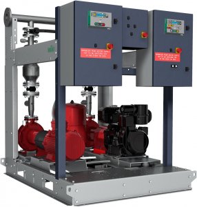
Design
Pressure-boosting systems for firefighting according to EN 12845. Consists of 1 or 2 pumps, depending on the module, with horizontal base plate — EN 733 — with spacer coupling, electric or diesel motor and a multistage, vertical electric jockey pump.
Application
Fully automatic water supply for fire-extinguishing systems with sprinklers in domestic, commercial and public buildings, hotels, hospitals, shopping centres and industrial buildings.
Equipment/function
- 1 or 2 pumps with horizontal base frame of series 32-200 to 100-250, with IE-equivalent standard motor or diesel motor
- With a diaphragm installed directly on the main pump housing to prevent overheating in the event of zero flow
- Jockey pump of series MVIL-1 or MVI-1with pressure switch and vertical pressure vessel 20 l, PN16
- One switch cabinet per pump, fixed to a robust support structure. EC Fire model: E for the electric motor and D for the diesel motor, both equipped with Easy Controller, plus J for the jockey pump
- Base plate made of electro-galvanised steel with height-adjustable holder for the outlet manifold
- Pipework made of steel; painted with epoxy resin. Manifold with flanges
- Shutting gate with safety lock on the discharge side of each pump
- Non-return valve on the discharge side of each pump
- A circuit with dual pressure switch, pressure gauge, non-return valve, valve for the main pump and standby pump for automatic start
- Concentric cone on the discharge side of the main and standby pump, for speed limitation according to the parameters specified in EN 12845
- DN2″ connection for the supply tank of the pumps
- Pressure measurement on the discharge side
- Only for the model with diesel motor:
- Vibration damping sleeve on the discharge side of the pump
- Vibration damper under the base plate of the pump
- Fuel tank with level sensor and sufficient volume for six hours of autonomous operation
- Two batteries on the base frame and battery charger in the EC-Fire switchgear
- Accessories on request:Note on fluids: Approved fluids are generally waters which do not attack the materials used, neither chemically nor mechanically, and do not contain any abrasive or long-fibre constituents. System in accordance with EN 12845
- Horizontal 500 l supply tank, with float valve and pressure switch for LL-alarm (water shortage)
- Flow meter: Kit with eccentric cone on the suction side, complete with check valve with hand lever or handwheel
- Vacuum gauge with valve
- Valves with electrical contact
- Vibration damping sleeve for the manifold
- Remote control panel for transmitting level A and level B alarms
- Density meter for the battery
- Spare parts kit for the diesel motor
- Silencer (30 dBA) for the diesel motor
- Hydraulic heat exchanger for the diesel motor
Typekey
Example: |
Wilo-SiFire Easy 40/200-180-7.5/10.5 EDJ |
SiFire |
Compact pressure boosting system for fire fighting equipment |
Easy |
Easy handling and in accordance with standard EN 12845 |
40/200 |
Type of main pump |
180 |
Actual impeller diameter of the main pump |
7.5 |
Power of the electric motor [kW] |
10.5 |
Power of the diesel motor [kW] |
EDJ |
Configuration |
E |
One electric pump |
D |
A diesel pump |
J |
A jockey pump |
Technical data
- Mains connection 3~400 V, 50 Hz (1~230 V, 50 Hz for the control panel of the diesel pump)
- IE equivalent standard motors, diesel motor with direct injection or turbo diesel motor with air or water cooling
- Max. ambient temperature +4 °C to +40 °C (+10 °C to +40 °C, if a diesel pump is installed)
- Max. fluid temperature +25 °C
- Max. operating pressure 10 or 16 bar
- Max. inlet pressure 6 bar
- Volume flow 10 m³/h to 750 m³/h
- Max. delivery head 128m
- Nominal connection diameters on the discharge side DN 65 to DN 250
- Nominal connection diameters on the intake side DN 50 to DN 200
- Switch cabinet protection class IP54
- Main/standby pump with horizontal base frame in accordance with EN 733
- With epoxy resin painted piping and hydraulic connections
- Permissible fluids: Note on fluids: Approved fluids are generally waters which do not attack the materials used, neither chemically nor mechanically, and do not contain any abrasive or long-fibre constituents. System in accordance with EN 12845
- Non-aggressive, clean water
- Firefighting water
Materials
For the pump with horizontal base frame
- Impellers made of stainless steel AISI 316/ 1.4401
- Pump housing made of grey cast iron EN-GJL-250
- Shaft made of stainless steel AISI 431/ 1.4057
- Wear rings made of bronze
For the jockey pump
- Impellers made of stainless steel AISI 304/ 1.4301
- Pump housing made of grey cast iron EN-GJL-250 (stainless steel AISI304/1.4301 for MVI)
- Shaft made of stainless steel AISI 304/ 1.4301
- O-ring seals made of EPDM
Construction
- Base frame: Manufactured from profiles consisting of electro-galvanised steel with brackets for the switch cabinets and the outlet manifold. Special square holes at the bottom for forklift trucks, as well as integrated hooks for lifting slings. Side profiles at the top on each side to enhance the rigidity of the system when moving and lifting.
- Plastic cover at the rear which provides visual access to the valve position and pressure gauge.
- Pipework: Complete pipework with flanges made of epoxy resin painted steel, suitable for the connection of all common piping materials; the dimensions of the pipework must correspond to the overall hydraulic performance of the pressure boosting system
- Pumps: 1 or 2 pumps with horizontal base frame — EN 733 — with spacer coupling, electric or diesel motor.
- • Back-pull-out model to ensure the internal parts of the pump are easy to access without having to move the motor or piping.
- Valves: The main pumps are fitted with a shut-off valve and non-return valve on the discharge side, both of which are painted with epoxy resin and adapted for a flange connection.
- Diaphragm pressure vessel: Diaphragm pressure vessel 20 l/PN16, on the discharge side of the jockey pump, with drain plug.
- Tank: The fuel tank is made of metal painted with epoxy resin and is located behind the bracket of the switch cabinet
- Sensors and display: 2 pressure switches, 2/16 bar per pump, on the discharge side, for activating the pump start via the EC-Fire controller and regulator. The discharge side pressure gauge (∅ 63 mm) is located in the middle of the rear panel.
- Controller: The system is equipped as standard with a separate switchgear/control device (EC Fire) for the electric or diesel motor and a switchgear/control device for the jockey pump.
Scope of delivery
- Factory-mounted, ready-for-installation pressure boosting system, which has been checked for functionality and impermeability
- Installation and operating instructions
- Required accessories on request